Table of Contents ECSS Model Page
Background Information Background Information
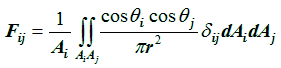
View Factor Calculation

Table of contents

Introduction
The SPENVIS View Factor calculator
Predefined configurations
Shapiro(1983)
Micro-VCM
ASTM-E-1559
Cube
References

Introduction

The computation of view factors is a key element in spacecraft contamination due to outgassing of materials. By definition the view factor Fij between two surfaces i and j, is the fraction of radiation leaving surface i that is intercepted by the surface j, and is given by:

where δij is determined by the visibility of dAj to dAi i.e. = 1 if dAj is visible to dAi and = 0 otherwise. The corresponding geometry is given in figure 1. Several methods to compute the view factor have been presented and discussed by G. Walton (2002).

Geometry and nomenclature view factors
Figure 1. Geometry and nomenclature for calculating view factors between finite areas.

The SPENVIS View Factor calculator

The SPENVIS tool calculates the view factors between the surfaces of a given configuration as follows:

Each surface is triangulated according the Delaunay algorithm in order to avoid skinny triangles. The triangulation is stopped when a minimal triangle area is reached. The minimum area is an input parameter set by the user. The default value is 10% of the surface area. The triangles can be considered as elemental areas. The view factor between each pair of surfaces is then given by the sum of the view factors between each pair of triangles. We remark that in generating the geometry configuration each surface is flat and has only one active side. The surface normal follows from the order of the vertices and using the right hand rule.
Once each surface has been divided into subfaces, we check for visibility between each pair of triangles by constructing rays between the centroids of these areas and between each of the vertices of triangle i to each of the vertices of triangle j. If there is no obstruction we perform a double line integration, otherwise a double area integration. In both cases the numerical integration is Gaussian. For triangles with a common edge we apply a single area integration. To assure some integration convergence we put a tolerance on the difference between successive computed values of the view factor. If the tolerance is not met, either the edges of the triangles are divided in subsegments or the triangle is further divided into subtriangles until an acceptable convergency is reached. The tolerance value is an input parameter for the user. The default value is set at 10-4.
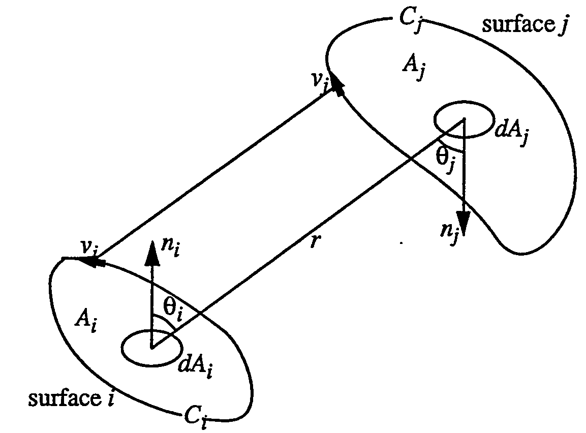
Predefined configurations

Shapiro(1983)

In 1983 Shapiro presented a configuration of surfaces (see figure 1) that has an analytic solution for an obstructed view factor. The configuration consists of two directely opposed unit squares (= surface 1 and 2) with unit separation and a pair of back-to-back 0.5 x 0.5 squares (surfaces 3 and 4) parallel to the unit squares, centered on a line between the centers of the unit squares, and 3/4 of the distance from surface 1 to surface 2. The analytic solutions are:

Fi,j 1 2 3 4
1 0 0.11562061 0.08420429 0
2 0.11562061 0 0 0.19861318
3 0.33681717 0 0 0
4 0 0.79445272 0 0

Shapiro (1983) configuration
Figure 1. Shapiro (1983) test configuration for obstructed view factors.
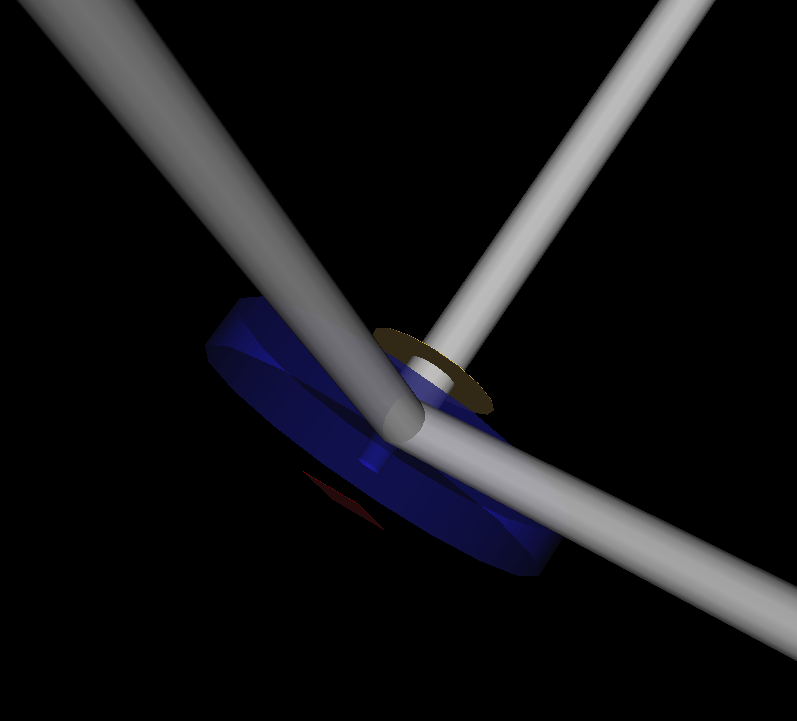
MicroVCM

Outgassing tests at ESA are performed with the Micro-VCM apparatus depicted in figure 2.1. The implemented configuration (figure 2.2) consists of one collector (yellow circular surface), a cover (blue hollow cylinder) with the orifice at the center and an emitter (red rectangular surface) beneath it.

Micro-VCM equipment ggt presentation of Micro-VCM equipment
Figure 2.1. Micro-VCM equipment. Figure 2.2. Implemented configuration.

ASTM E 1559

ASTM E 1559, is a standard test method for contamination outgassing characteristics of spacecraft materials, published by the American Society for Testing and Materials but originally developed under a program sponsored by the United States Air Force Materials Laboratory (AFML). A schematic of the measurement method is shown in figure 3.1. The outgassing material sample is held in vacuum in a temperature-controlled effusion cell, while its outgassing flux impinges on several QCMs (Quartz Crystal Microbalances) which view the orifice of the effusion cell. The implemented configuration (figure 3.2) consists of four collectors (yellow circular surfaces), a cover (blue hollow cylinder) with the orifice at the center and an emitter (red rectangular disk) beneath it.

ASTM E 1559 schematic ggt presentation of ASTM E 1559
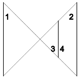
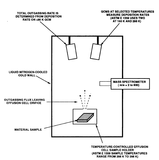
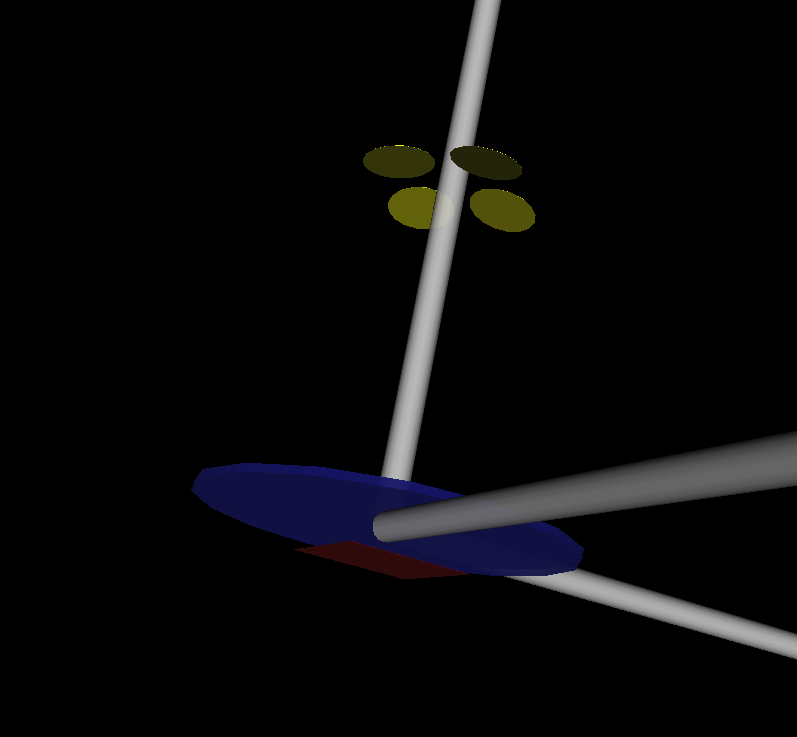
Figure 3.1. Schematic of the measurement method used for ASTM E 1559. Figure 3.2. Implemented configuration.

Cube

The inner surface of a cube is considered for computing the view factor. Theoretically the total view factor from one face to all others is equal to 1, however due to numerical computation the result may deviate a few percent. The dimensions of the cube are 1x1x1 (see figure 4).

1x1x1 cube
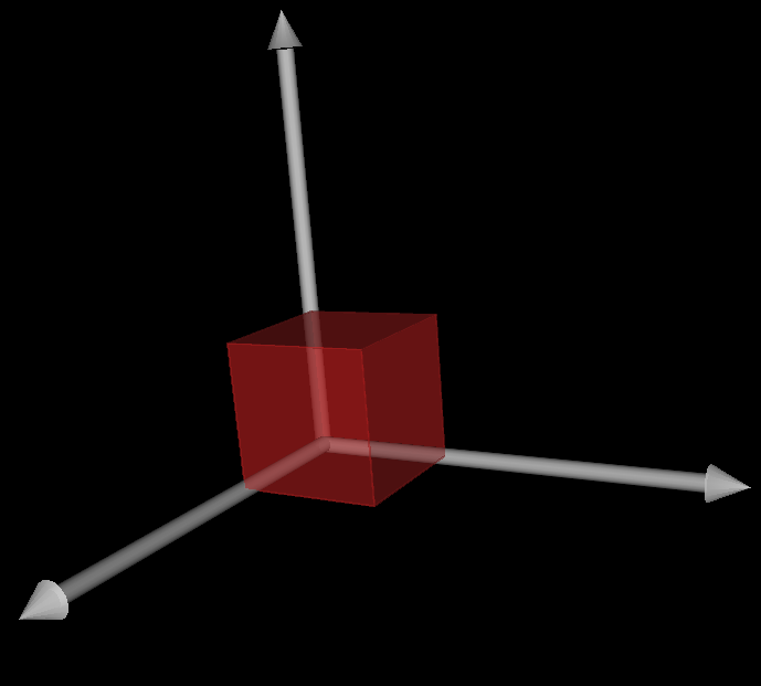
Figure 4. 1x1x1 cube.

References

ECSS-Q-ST-70-02C, 15 November 2008.

J.W. Garret, P.M. Glassford, and J.M. Steakley, "ASTM E 1559 Method for Measuring Material Outgassing/Deposition Kinetics", Lockheed Missiles & Space Company Inc., Sunnyvale, CA.

A.B. Shapiro, "Computer Implementation, Accuracy and Timing of Radiation View-Factor Algorithms", Technical Report UCRL-89602, ASME winter annual meeting, Boston, MA, USA, 13 Nov 1983.

G. Walton, "Calculation of Obstructed View Factors by Adaptive Integration", NIST Report NISTIR-6925, 2002, see also http://view3d.sourceforge.net/


Last update: Mon, 12 Mar 2018