 indicates dielectric and
  indicates
conductor:
| Table of Contents | ECSS | Model Page |
| Background Information | Spacecraft charging | |
| Spacecraft charging: DICTAT | ||
DICTAT calculates the electron current that passes through a conductive shield and becomes deposited inside a dielectric. From the deposited current, the maximum electric field within the dielectric is found. This field is compared with the breakdown field for that dielectric to see if the material is at risk of an electrostatic discharge.
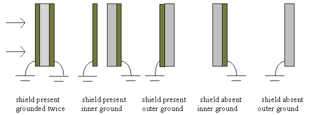
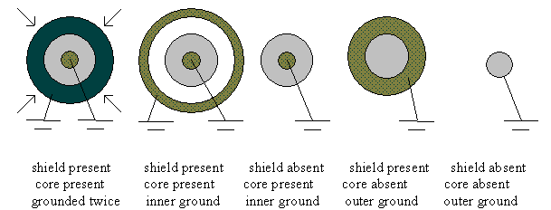
The user inputs details of the structure to be simulated. The tool allows both planar and cylindrical structures, made up of a single dielectric and a shield. An absent or negligibly thin shield may be simulated by defining a shield of zero thickness. The dielectric may be grounded on both surfaces or on either the outer surface (nearest the environment) or on the inner surface.
This allows the following planar structures to be treated where
 indicates dielectric and
  indicates
conductor:


If the structure is predicted to exceed the breakdown threshold, then the tool will suggest changes to the shield and dielectric thicknesses that would bring the structure safely below the threshold.
In order to produce a fast user friendly tool, the code uses analytical approximations to calculate electron transport through the shield and deposition in the dielectric. This is not the most accurate way this could be done. However, a more critical complexity in the internal charging problem lies in the changes that take place in dielectric conductivity in space. Here the tool includes all the important physical processes: radiation, temperature and electric field effects on conductivity. Because the best equations describing these effects are primarily empirical and approximate, this aspect of the calculation does not justify a more detailed current deposition analysis.
Although the main output of the code is a statement on whether the dielectric is likely to discharge or not, this assessment is based purely on whether the maximum electric field exceeds the breakdown threshold for the dielectric. Other types of discharge are possible, particularly discharge from a high-potential surface across a gap. The probability of this discharge depends on the details of the geometry of the structure and the surrounding structures. The code makes no assessment of these. However, the code does output the surface potential which should enable the user to assess whether a surface discharge is a possibility. Typically a surface potential of hundreds of volts should be a cause for concern.
Finally, as for most simulation programs, DICTAT results depend strongly on the quality of the input data. Dielectric material properties, e.g. bulk conductivity and breakdown electric field, are hard to obtain and may vary by orders of magnitude from one sample to the next. The tool is supplied with a list of representative parameters for a number of materials but the user may need to change these to worst-case values or as the result of a well conducted experimental measurement.
Electrons are not all deposited within the material at range R. Instead,
there is a fall-off in the beam current in an approximately linear fashion,
over distance a, estimated by Sorensen [1996] as:
These equations are implemented in the code to give the current through a given surface, as follows:
This is the complete current calculation for the unidirectional beam at normal
incidence but for the omnidirectional environment, there is a further iteration
over angle. The range of angles is defined by the user (default is 90°). To
determine the range R, the range at normal incidence must be divided by
costheta, where theta is the angle to the normal. Total flux
through each surface is found for the range of angles in 9 equal steps. The
contribution each angle makes to the total current J is as
follows:
 .
.
 .
.
For planar geometry, this scheme is straightforward and does not produce a
substantial overhead in terms of run-times. For cylindrical geometry, the
structure is also divided into 20 sectors, at varying distances y from
the centre of the core. The total thickness t of material contained
within a surface at radius r is
The cylindrical simulations do not take into account any spreading of the beam as it passes through the shield and dielectric. This is implicitly included in the planar case because the equations for R and for a arise from planar Monte Carlo simulations where scattering of the beam is included. The effect on the cylindrical geometry may be to smear out charge distributions where the electrons penetrate deeply into the dielectric. However, as the charge distribution is expected to be quite uniform in such cases, the effect may not be large.
For a singly grounded dielectric at equilibrium, all deposited current must flow towards the only ground. For a doubly grounded dielectric, the code assumes that current will flow only to the nearest ground. Because even a mono-energetic beam produces a very wide deposited current distribution, this approximation works very well where the dielectric conductivity is uniform. Where radiation and electric fields create differences in conductivity, the approximation becomes imperfect but remains adequate.
The current in each sub-zone is found by summing, from all the zones, the currents that must pass through that zone to reach ground. Hence, the charging current is the sum of current deposited in all 10 sub-zones in a singly grounded structure and in only 5 in a doubly grounded one.
The code defines the charging current to be the maximum equilibrium current flowing at any location. For a singly grounded dielectric this is the sub-zone adjacent to the grounded surface. For a doubly grounded dielectric it is assumed to be the sub-zone adjacent to the front surface.
The effect of the electric field can be included using another formula based on
work by Adamec and Calderwood [1975]:
Radiation dose-rate induced conductivity is given by the empirical formula sigma(J) = kpDDelta, where D is the dose rate (in rads·s-1) and kp (in Ohm-1·m-1·rad-Delta·sDelta) and Delta are measured constants of the material. The dose rate is the rate of radiation energy deposited in the dielectric. The code ignores the effects of protons, cosmic rays and gamma rays on dose rate and determines it solely in terms of the electron population. This is reasonable since the outer radiation belt, where internal charging is significant, is dominated by electrons.
By approximating the energy deposited by the electrons per second to be independent of energy, the following relation is found: D = 1.92x10¹¹ J with J the current density in A·m-2. Some evidence has been given in the literature of a total dose effect on conductivity. However, this effect does not appear to be well-established and is not simulated in the code.
Dose-rate induced conductivity is treated by the code as an additional component of conductivity to the temperature and electric field dependent component, i.e. sigma = sigma(E,T) + sigma(J) in Ohm-1·m-1.
It should be noted that the parallel plate approximation is applied to both planar and cylindrical cases. A more exact time dependence for cylinders is a possible improvement for a future version of the code.
The model consists of fits to the most intense electron enhancements from 1987 to 1998. Data from GOES-7, the LANL Energetic Spectrometer for Particles (ESP) on a number of geostationary spacecraft and the REM instrument on STRV-1b were used. The model spectra at GEO and their dependence on flux were based on data from the ESP instruments. L dependence on intensity and spectrum was based on data from severe outer belt enhancements observed by the REM instrument [Desorgher et al., 1996] on STRV-1b. The solar cycle and seasonal dependence is based on >2 MeV fluences, observed at geostationary orbit by GOES-7. The construction of the model followed a study [Wrenn et al., 1999] in which the different data sets were characterised and compared to ensure that they were compatible.
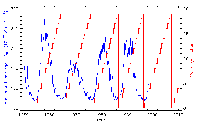
The environment model takes as input L, B/B0, fraction of solar cycle (FSC) and fraction of year (FYR). All these parameters can be defined by the user or calculated by the code from orbital parameters. FSC is based on a 20-segment scheme devised by Vampola [1996], and starts at solar minimum (see Fig. 1). Solar maximum is at FSC=0.35 and the most intense fluxes are seen at FSC around 0.8.
 |
| Figure 1. Three month averaged solar radio flux and Vampola's [1996] solar cycle phase |
In the SPENVIS implementation, the user can directly specify a (B/B0,L) pair, or ask the system to use orbit parameters to generate one orbit. In the latter case, L and B/B0 are calculated from the spacecraft position, using the Tsyganenko [1989] model and IGRF 1994 internal field model. The system determines the solar cycle phase, which is taken to be constant over one orbit, and the fraction of year, from the orbit epoch. The spacecraft positions are generated independently of the orbit trajectory generated by the orbit generator. No account is taken of atmospheric drag or perturbations caused by the Moon, the Sun or oblateness of the Earth. Forty positions per orbit are calculated.
The method used is based on finding the equilibrium value of the field using the user-defined spectrum or, where an orbital simulation was requested, the environment which caused the maximum electric field. Using equilibrium values may make the result over cautious when a short time duration has been specified.
The new shield thickness is found as follows:
This method is quite fast as 3 or 4 iterations are usually sufficient. However, for the cylindrical geometry, each of these iterations requires the recalculation of the array of thicknesses for the 200 segments/sub-zones pairs. This makes it slower than the planar case.
Desorgher L., P. Buehler, A. Zehnder, E. Daly, and L. Adams, Outer Radiation Belt Variation during 1995, in Environmental Modelling for Space-based Applications, ESA SP-392, p. 137, 1996.
Rodgers D.J., K.A.Ryden, G.L.Wrenn, P.M.Latham, J. S&oring;rensen, L.Levy, An Engineering Tool for the Prediction of Internal Dielectric Charging, 6th Spacecraft Charging Technology Conference, Hanscom, 1998.
Rodgers D.J., K.A.Hunter and G.L.Wrenn, The FLUMIC electron environment model. Proceedings 8th SCTC, Huntsville, 2003.
Rodgers, D. J., DICTAT Software: Users' Manual, Issue 3.0, DERA/CIS(CIS3), 1999.
Rubin A.G., I. Katz, M.J. Mandell, G. Scnuelle, P. Steen, D. Parks, J.J. Cassidy, and J.C. Roche, A 3-Dimensional Spacecraft Charging Computer Code, in Space Systems and their interactions with the Earths Space Environment, H.B. Garrett and C.P. Pike (eds.), Progress in Astronautics and Aeronautics, vol. 71, AIAA, 1980.
Sorensen J., An Engineering Specification of Internal Charging, in Environmental Modelling for Space-based Applications, ESA SP-392, p. 129, 1996.
Soubeyran, A., and R. Floberhagen, ESA-DDC 1.1 User Manual, Matra Marconi Space, 1994.
Trenkel, C., Comparison of GEANT 3.15 and ITS 3.0 Radiation Transport Codes, ESA working paper, EWP 1747, 1993.
Tsyganenko, N.A., A magnetospheric magnetic field model with a wrapped tail current sheet, Planet. Space Sci., 37, 5-20, 1989.
Vampola, A. L., The ESA Outer Zone Electron Model Update, in Environment Modelling for Space-based Applications, ESA SP-392, pp. 151-158, 1996.
Weber, K.-H., Nucl. Inst. Meth. 25, 261, 1964.
Wrenn G.L., and A.J. Sims, Surface Potentials of Spacecraft Materials, Proceedings of the ESA Workshop on Space Environment Analysis, ESA WPP-23, p. 4.15, 1990.
Wrenn G.L., D.J. Rodgers, and P. Bühler, Modelling the outer belt enhancements of MeV electrons, J. Spacecr. Rockets, Vol. 37, pp 408-415, 2000.
Last update: Mon, 12 Mar 2018