E.2.3 Solar array test procedure
E.2.3.1. Preliminary set-up
The set-up includes the following steps:
• Coupon preparation
• The solar cells’ current-voltage (I,V) characteristic are measured with the help of standardized flasher tests. Visual inspection and electrical continuity control are achieved.
• The gap sizes between the strings are measured.
E.2.3.2. Test on polarized solar array coupon in vacuum
The following is a description of the test for the inverted voltage situation with electron irradiation. When another method is used, this procedure is modified consequently.
• Out-gas the coupon in the best possible vacuum (< 10-6 mbar) for 10 or 12 hours.
• Apply the bias (-5 k V) to the coupon structure with a power supply through a resistor of 100 MW.
• Verify that no discharge appears (with the help of Pearson probes and video recording).
• Irradiate the coupon (solar cell side) with 8 keV electrons at low current density (few tens of pA/ cm²) to obtain the inverted voltage gradient until primary discharges appears. (Other triggering methods are possible.)
• Verify that at least 5 primary discharges occur in the intercell gap.
• After exposure, verify that all strings are isolated from each other and from the structure (nominal resistance is > 1 MW).
• Power the solar cell string with an ESD representative Solar Array Simulator at nominal interstring voltage and nominal string current, including margin and the switching transients (overshoot) due to the operation of the power regulator.
• Record a few typical discharge signatures (I(t), V(t)).
E.2.3.3. Success criteria
The success criteria for testing are the following:
• Success in the standardized flasher test.
• Success of electrical continuity checks.
• Success of electrical insulation checks.
• Success of visual inspection (no visible degradation)
NOTE It is important to pay attention to the heating of the cells. It is generally not feasible to bias the cell strings with the nominal current, so a low current source should be used for voltage biasing.
E.2.3.4. Electrical parameters of the coupon
All the following electrical parameters of the solar array string in its environment are carefully determined and simulated on the coupon.
• String and section voltages.
• String and section currents.
• Solar array absolute bias voltage (-5 kV worst case for geostationary orbit).
•
Spacecraft absolute capacitance
Csat (see .Figure
E-5)
This is the capacitance of the satellite structure to infinity. On the
geostationary orbit 200 pF is a typical value.
Figure E-5: Absolute capacitance of the satellite
•
Solar array absolute capacitance
CSA.
This is the capacitance of the panel structure to infinity. On the
geostationary orbit 100 pF is a typical value.
It is known today that the satellite capacitance plays a role of prime importance
in the ignition of the inverted voltage gradient discharge and that its value
is low (typically 300 pF). It is also know that the representativity is
achieved by taking into account the true capacitance value of the satellite
without adding the coverglasses capacitance in parallel to it. It can lead to
false transient response.
• Structure-string capacitance: common mode capacitance measured between the short circuited solar cell string and the solar panel structure.
•
For Kapton capacitance CKfor one cell
(typical value Ck/Area=15 to 30 pF/cm²) deduced from the following
formula ![]() for area A and
thicknes d.
for area A and
thicknes d.
To get to the right value, the best solution is by network analyser
measurements.
•
For the capacitance through the Kapton for the missing cells (Cstring
com), the capacitance between the string and the structure through the
Kapton is evaluated. Cstring com is chosen at its highest possible
value which is ![]() ,
where Ns is the number of cells per
string and Np is the number of
strings in parallel.
,
where Ns is the number of cells per
string and Np is the number of
strings in parallel.
•
String capacitance:
differential mode between the two ends of the string.
The capacitance of the missing cells chain is simulated by only one capacitance
between the (+) and the (-) wires. In the case of a floating solar array
structure (during fast transients, when there is a bleeder resistor), we can
approximate the impedance of the SA by a capacitance:
It is important to take the right value of the Cell junction capacitance
due to its non-linearity (estimation of the capacitance for voltage values
between 0 and Vnominal, see Figure
E-6). 
For high value of CJ, (Si cells near Voc: open circuit
voltage) ![]() then,
then, ![]()
As there are about one hundred cells per string, you have ![]() . This is the case when CString Com is
negligible, the equivalent capacitance of a whole string corresponds to the
capacitances of each cell (Cc) in series.
. This is the case when CString Com is
negligible, the equivalent capacitance of a whole string corresponds to the
capacitances of each cell (Cc) in series.
For low value of Cj, ![]() then
then ![]()
Most of the time, the Cj value is intermediate and therefore the complete
equation for the capacitance is used.
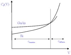
Figure E-6: Junction capacitance of a cell versus to voltage
• String inductance. The capacitances are put as close of the coupon as possible (on the rear face of the coupon inside the vacuum chamber), connected to the cells with simple wires. The length of those wires simulate the whole string impedance whose typical value is below 1 µH (which authorizes a length of around 1 m).
•
The capacitance of the cover-glass. Coverglass capacitance is capacitance measured between the front
face of the cell and the front face of the coverglass. This capacitance is not
taken into account in the calculation of the spacecraft capacitance. ![]() where A and d are the area and thickness of the coverglass respectively.
where A and d are the area and thickness of the coverglass respectively.
This capacitance is
evaluated for each coverglass. In fact it is hard to insert it in the test
set-up. It is important to note that this capacitance cannot be added to the
satellite capacitance. A metallic electrode cannot be used, and a large enough
dielectric is used for the tests. The best solution seems to use a power source
between the “+” wire and an electrode beyond the cell. This source delivers an
equivalent current to the flashover current to that delivered if the coverglass
were neutralized.
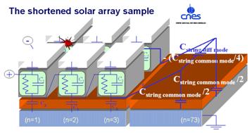
Figure E-7: The shortened solar array sample and the missing capacitances