E.2.2 Pre-testing of the solar array simulator (SAS)
E.2.2.1. General
The coupon alone does not display the same electrical response as a whole solar array. Hence a circuit, called a solar array simulator is set up. A solar array simulator is able to reproduce the dynamic response of an illuminated solar array to transient short-circuits between cells. This particularly requires that high current can be supplied as soon as a short-circuit occurs.
It is intended that the dynamic response of the solar array simulator is the same as the string response during the first microsecond. The quality of the solar array is evaluated with a specific test set-up. To test the time response of the various power supplies, the test set-up below can be used.
The test is performed with the same wire length as used during the solar array test or, better yet, directly in the vacuum chamber just before making the test. The real set-up is used and the real slope of the transient is known. It is suggested to start always with this kind of test to evaluate the effect of the set-up on the transient response of the solar array.
To evaluate only the power supply, a test can be done with a set-up with wire length as short as possible. The success criterion is achieved when the transition is made in less than one microsecond.
The test procedure is as follows (see Figure E-2):
• The power supply voltage is adjusted to 50 V and the current limited to 3 A. The current flowing through the 50 W impedance is equal to 1 A.
• The 50 W impedance is suddenly short-circuited with a 1 W impedance (using a mercury switch to avoid rebound). The power supplies then switch from voltage limitation state to current state. We therefore see the current pass from 1 A to 3 A.
• Wire length is chosen so that total inductance does not exceed 1 µH. If the wires are too long, the maximum rise slope that can be measured is fixed by their length and the real rise time of the power supply is not achieved.
• Only a power supply with very low output capacitance is used. If this is not possible, an electronic current regulator is used to conceal the capacitance.
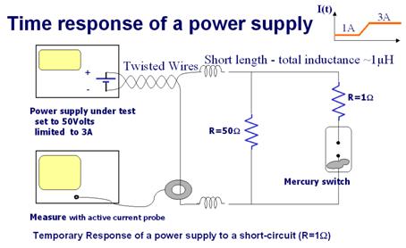
Figure E-2: Schematic diagram of power supply test circuit
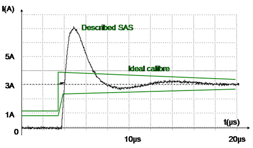
Figure E-3: Example of a measured power source switch response
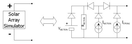
E.2.2.2. Example SAS
Any SAS that meets the success criteria can be used. The description in Figure E-4 is given as an example. This SAS set-up allows us to choose both the voltage between the two end cells of a string and the current through the cells.