Introduction
Most operational spacecraft have power generation capabilities of the order of
a kilowatt or less and low voltage distribution systems. Typically, electrical
distribution system voltages of 28 volts and solar array operating voltages of
30 to 36 volts are used. However, for large space platforms such as the Space
Station, the substantially higher power levels to be incorporated will require
very much higher voltages for the solar array and associated electrical
distribution system. This is simply to avoid transporting large electrical
currents with the attendent large bus bar dimensions and high resistive power
losses.
Because the ambient plasma density in LEO is not negligible, any structure with
high voltages will interact with the plasma environment as electrons are
attracted to positive surfaces and ions are attracted to negative surfaces. The
voltages of various parts of the structure and solar array, relative to the
local plasma potential, will depend on the configuration of electron and ion
collecting surfaces, the voltage difference between such surfaces, and the
nature of the plasma environment. The structure will, in other words, float at
some specified potential relative to the plasma potential, with the solar array
floating at various potentials dependent on the position along the array that
one considers. Figure 1 illustrates this phenomenon for a structure grounded to
the negative end of the solar array.
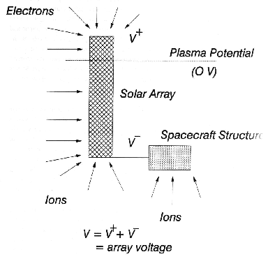 |
| Figure 1. Illustration of a solar array/spacecraft
structure configuration floating relative to the ambient plasma
potential |
There are several important consequences of the above plasma interaction
effect. Because it is so much easier for a surface of given dimensions to
collect electrons than ions (due to their different masses) the bulk of the
solar array will float negative. If the spacecraft structure is connected (or
grounded) to the negative end of the solar array then it too will float
negative with respect to the plasma potential. If an approaching space vehicle,
such as the Shuttle for example, tries to dock with the structure then there
may be a significant transfer of charge between the two vehicles since the
approaching spacecraft will be at, essentially, plasma potential. In addition,
the negative end of the solar array (and the structure if it is grounded to it)
will accelerate ions from the plasma to an energy approximately equivalent to
its voltage relative to the plasma potential. Since this may be over a hundred
volts, significant erosion may take place over a period of time since 100 eV
ions are well above any materials sputtering threshold. This may be very
important if the sputtering takes place in areas where sensitive surface
coating exists.
In addition to the effects described above there are a number of other plasma
interaction phenomena, such as discharges during outgassing and breakdown of
dielectric surfaces. The important point to note is that a detailed
understanding of these interaction phenomena is a crucial part of the early
design phase of such programmes.
The solar array/space plasma interaction model
Introduction
The solar array/space plasma interaction model SOLARC is part of the
ESPIRE suite of
programmes for analysing spacecraft/plasma interactions. SOLARC simulates the
current collection, voltage distributions and material
erosions on solar arrays and spacecraft structures in a space environment.
In order to do so, the code requires a
description of the plasma environment, a description of the solar array
spacecraft structure configuration and models which describe the way the
various surfaces collect ions and electrons. The core of the program is
concerned with determining the potentials of the solar array and structure
relative to the plasma potential.
Any exposed conducting surface at a given voltage V will see a collected
current composed of contributions due to ions, Ii, and
electrons, Ie:
Icol(V) = Ie -
Ii .
The relative contribution of each component will depend on the voltage and will
be dominated by one component at large positive or negative voltages. The
contributions may be broken down as follows:
Ie = ie - iee -
ieb - iep ,
Ii = ii + iei ,
where ie is the electron current to the surface,
iee is the secondary electron current from the surface due to
the electrons, ieb is the backscattered electron current,
iep is the photoemission current from the surface,
ii is the ion current to the surface, and
iei is the secondary electron current from the surface due to
the ions. The current collection is illustrated in Fig. 2.
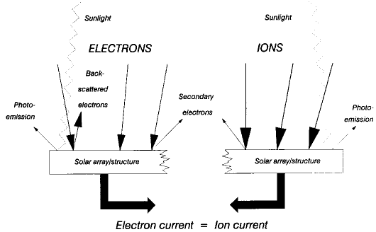 |
| Figure 2. Schematic illustration of current collection
by a solar array and platform structure |
In equilibrium the net current to the spacecraft including the solar array must
be zero and, therefore, the sum of the collected current at each surface of
given voltage must be zero. If the collected current, at any point, is known as
a function of voltage, then the equilibrium distribution of potentials on the
solar array and spacecraft structure may be found by adjusting the potentials
until this condition is satisfied. This is done ietratively within the program
until some convergence level is reached.
Once the potentials on the spacecraft and solar array have been determined,
other calculations may be performed such as determining the
plasma current and
calculating the erosion on particular surfaces.
From the above discussion, it will be clear that a crucial part of obtaining
realistic results is the precise nature of the function used to determine the
collected currents. These so-called current collection models are described
below.
Current collection models
The current collected by a surface depends in detail on the physical
characteristics of the surface (materials properties and geometry) and the
local plasma environment. Consequently, to accurately simulate the current
collection would require simulating secondary electron emission, photoemission,
backscattering, and the detailed characteristics of the local plasma
environment (particle fluxes, density, temperatures, etc.). Many of these
characteristics are highly dependent on particle energy and type. Whilst such
calculations are posssible, they are very time consuming and can only be done
for small (in terms of Debye length) objects. Moreover, even these calculations
often require simplifying assumptions to be made in, for example, the geometry
of the objects. Fortunately, there is an alternative way of tackling the
problem which is appropriate to a fast, zero order computer code such as
SOLARC. This is by defining, a priori, a set of empirical current collection
relationships.
The current collection relationships used by SOLARC are simply expressions that
define the ratio of the actual to ambient current density collected by a
surface at a given potential. The generalised current collection expression
used by SOLARC is
J/J0 = a1 + a2
{a3 + a4
[e(|V|-a5)/E]alpha1}alpha2
+ b1 exp[b2
e(|V|-b3)/E] ,
where E is the particle energy, V is the surface voltage,
J0 is the ambient current density, and J is the actual
current density. The parameters an, bn, and
alphan are user specified and
allow various current
collection models to be constructed. Once the collected current density has
been calculated the actual collected current can be obtained simply be
multiplying by the surface area. One should note that current collection models
can be specified for both ions and electrons.
The ambient current density J0 is defined as
J0 = e F0 ,
where F0 is the ambient flux of particles. For a thermal
distribution of ions or electrons, F0 is given by
F0 = n/4 (8kT/pi m)0.5 ,
where n and T are the particle density and temperature,
respectively, and m is the particle mass.
Four pre-defined current collection models are implemented in SOLARC. These are
described below, and are plotted in Figs. 3 and 4.
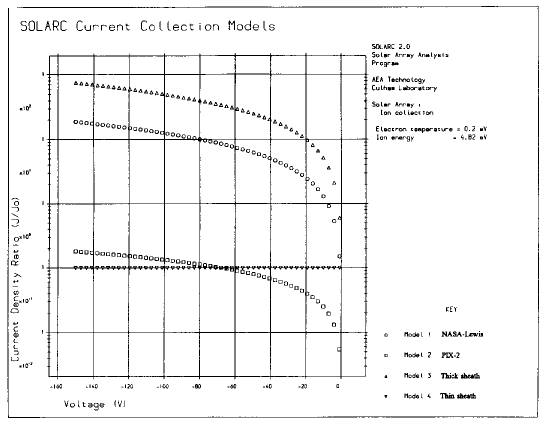 |
| Figure 3. The four ion current collection models used
by SOLARC |
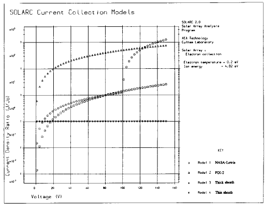 |
| Figure 4. The four electron current collection models
used by SOLARC |
Model 1
The first current collection model is that produced by Viswanathan et al.
(1985) based on ground based solar array experiments undertaken at
NASA's Lewis Research Center. It has the form:
        J/J0 = 0                    V>0
        J/J0 = 0.25 (1+e|V|/kTi)    V<=0
for ions and
        J/J0 = 5 [1+e(|V|-100)/kTe]    V>100
        J/J0 = 0.025 (1+e|V|/kTe)      0<=V<=100
        J/J0 = 0                       V<0
Ti and Te are the ion and electron
temperatures (K), respectively. This model is applicable to solar arrays in
which the interconnect area (the area of exposed conductor) is 5% of the
total solar array cell area.
Model 2
The second current collection model is due to Stevens (1986) and is derived
from data obtained on the PIX-2 spaceflight. It has the form:
        J/J0 = 0                          V>0
        J/J0 = 1.25x10⁻²(1+e|V|/kTi)3/4    V<=0
for ions and
        J/J0 = 2.5x10⁻⁴(5e|V|/kTe)3/2      V=>0
        J/J0 = 0                         V<0
for electrons. This model is applicable to solar arrays of the type used on
PIX-2 in a ram environment (i.e. directly exposed to the motion induced ion
flux) with an electron temperature of 0.2 eV.
Model 3
The third model is applicable to any surface and is based on a linear increase
in the electrostatic sheath with voltage. It has the form:
        J/J0 = exp(-e|V|/kTi)    V>0
        J/J0 = 1 + e|V|/kTi      V<=0
for ions and
        J/J0 = 1 + e|V|/kTe      V>0
        J/J0 = exp(-e|V|/kTe)    V<=0
for electrons. This type of current collection is sometimes referred to as
thick sheath current collection.
Model 4
The fourth and final current collection model is similar to the third model
except that this time the sheath thickness is assumed to be small relative to
the surface dimensions and independent of voltage. It has the form:
        J/J0 = exp(-e|V|/kTi)    V>0
        J/J0 = 1                 V<=0
for ions and
        J/J0 = 1                 V>0
        J/J0 = exp(-e|V|/kTe)    V<=0
for electrons. In contrast to Model 3 this type of current collection is
sometimes referred to as thin sheath current collection.
Material erosion and sputtering
Surfaces at negative potential relative to the plasma potential will accelerate
ions, principally oxygen ions, to an energy equal to the surface potential. If
this lies above the sputtering threshold then erosion of the surface will take
place, to an extent dependent on the energy of the ion, the flux of ions, and
the sputtering yield. To complicate matters there are two types of erosion
mechanism which, because of the presence of oxygen ions, both occur in the LEO
environment. The first of these mechanisms is known as chemical sputtering and
occurs because the oxygen ions react chemically with the surface of many
materials. Such erosion is dependent on the energy of the oxygen ion (or atom)
but in most cases does not show any threshold. The second type of erosion
mechanism is called physical sputtering and occurs as a result of the transfer
of momentum between the incoming ion and the atoms in the surface of the
material. Again it is energy dependent but has a threshold at an energy that is
typically around 30 to 40 eV. It is strongly dependent on the type of incident
ion and the type of surface material.
Modelling sputtering and erosion is not easy. However, there are a number of
semi-empirical models that may be used to perform calculations for a number of
incident ion/material combinations. SOLARC Has two such sets of semi-empirical
relationships. The first deals with physical sputtering of monatomic (i.e.
elemental) solids at normal incidence and the second deals with both chemical
and physical sputtering of Kapton (polyimide) by oxygen.
Physical sputtering of elements
Physical sputtering has received a considerable interest over the years because
of the number of areas of plasma physics in which it is important. For example,
considerable experimental and theoretical work has been done in support of
nuclear fusion research, with high bombarding energies in the range
102 to 106 eV. Matsunami et al. (1983) compiled a
comprehensive data base in this energy region, covering the sputter yields of
monatomic solids for over 250 ion-target combinations. An empirical formula was
devised to fit all the experimental data. Although giving a good fit at higher
energies, the fit is poorer for energies below 100 eV, in its original form.
This is partly due to a lack of data, but more importantly, the expressions for
the sputtering threshold were insufficiently accurate.
Bohdansky et al. (1980) suggested an analytical formula for sputtering at
energies below 2 keV, which took account of threshold energies, and this
Bohdansky model is widely quoted and used. However, the energies of particles
incident on solar array surfaces are close to threshold energies and,
therefore, accurate modelling of the yields near threshold is essential.
Further work was carried out by Yamamura and Bohdansky (1985), who produced a
fully analytical expressions for near threshold sputtering. Matsuno et al.
(1987), in a follow-up to the previous report, have used this improved
analytical formulation to improve the agreement of their empirical expressions
for low incident ion energy. This approach, based as it is on both analytical
and experimental data, is thought to provide the most valid sputter model
available near threshold. As a consequence, it has been used within SOLARC to
calculate the sputtering due to the impact of ions on the surfaces of a range
of monatomic solids.
In essence the sputtering yield Y (in terms of the ratio of sputtered
atoms to incident ions) is given by the semi-empirical formula
Y = 0.042 alpha*Q(Z2)
Sn(E) / Us /
[1+0.35Usse(epsilon)]
[1-(Eth/E)0.5]2.8
where E is the incident ion energy, Q(Z2) is a
target atomic number dependent property and alpha* is given
by
alpha* = 0.10 + 0.155
(M2/M1)0.73 + 0.001
(M2/M1)1.5
In this expression M1 is the incident ion mass and
M2 is the target atom mass. The nuclear stopping cross
section Sn(E) is given by
Sn(E) = K sn(epsilon)
where K is a conversion factor from the elastic stopping function
sn to the stopping power Sn in units of eV
cm2 10-16 atoms and is given by
K = 84.78 Z1 Z2 /
(Z12/3 +
Z22/3)1/2 M1 /
(M1+M2)
Z1 Z2 being the incident and target atomic
numbers.
The elastic stopping function sn(epsilon) is given by
sn(epsilon) = 3.441 epsilon1/2
ln(epsilon+2.718) / [1 + 6.355 epsilon1/2 +
epsilon(6.882epsilon1/2-1.708)]
where the reduced energy epsilon is expressed in terms of the incident
ion and target atomic masses and numbers as
epsilon = 0.03255 / [Z1 Z2
(Z12/3 +
Z22/3)1/2] M2 /
(M1+M2) E
in units of eV.
The parameter Us is the target material sublimation energy (in
eV) and, as the parameter Q, is supplied from a set of tables. The
inelastic stopping function se(epsilon), on the other
hand, is given by
se(epsilon) = k epsilon1/2
where
k = 0.079 (M1+M2)3/2 /
(M13/2 M21/2)
Z12/3 Z21/2 /
(Z12/3 +
Z22/3)3/4
Finally, the all-important threshold energy Eth is given by
      Eth = (4/3)6 Us/gamma                     M1=>M2
          = Us/gamma [(2M1+2M2)/(M1+2M2)]6       M1<M2
where
gamma = 4 M1 M2 /
(M1+M2)2 .
These equations constitute the physical sputtering model incorporated into
SOLARC and may be used to predict sputtering due to a wide range of incident
ion/target combinations. As an example, Fig. 5 shows the sputtering yield due
to the impact of oxygen of copper (physical sputtering only).
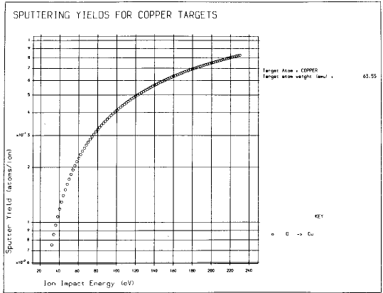 |
| Figure 5. The sputtering yield due to the impact of
oxygen on copper, calculated using the physical sputtering
model |
Erosion of Kapton (polyimide)
The processes involvedin the erosion of polymeric materials by oxygen are much
less well known than for the physical sputtering described above. For the case
of the erosion of Kapton by oxygen it is clear that both chemical and physical
erosion processes take place, depending on the energy of the incident oxygen
ion. Kapton erosion by oxygen has, in fact, received considerable attention
because of the erosion caused by the impact of atomic oxygen at low Earth
orbital speeds (typically equivalent to an energy of about 5 eV). Figure 6
shows a collection of data describing the erosion rate of Kapton due to the
impact of oxygen ions and atoms of various energies. The data comes from a
variety of experiments both ground and space based and is due to both ionic and
atomic oxygen. The straight line through the data is a completely empirical
expression due to Ferguson (1984) which gives the erosion rate R (in
units of amu/ion) as
R = 1.5 E0.68
where E is the incident oxygen energy in eV. This expression is used in
SOLARC to calculate the erosion of Kapton due to the impact of a given flux of
oxygen ions.
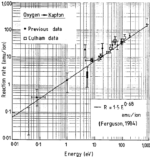 |
| Figure 6. The erosion rate of Kapton due to the impact
of oxygen ions and atoms. The straight line is the empirical expression
given by Ferguson (1984). |
Implementation in SPENVIS
Input
In performing an analysis in SPENVIS, the user
has considerable control over the specification of the plasma environment as
well as the configuration of the solar array and associated spacecraft. This
flexibility in the input to a simulation includes the following features:
- specification of a variety of solar array and spacecraft configurations;
- availability of a number of different pre-defined current collection
models;
- the ability to specify thermal and energetic distributions of ions and
electrons. A variety of ion types may also be selected.
Plasma environment description
The space plasma environment surrounding the solar array and spacecraft is
specified by a thermal ion and electron distribution and energetic ion and
electron spectra.
Thermal distributions
The thermal ion distribution is characterised by a temperature, a number
density, and an ion type. A selection of ion types (elements) is
available. The thermal electron distribution is characterised by a temperature
and a number density.
Energetic particles
The energetic ion spectrum is characterised by an energy, a particle flux, and
an ion type. The energetic electron spectrum is characterised by an energy and
a particle flux.
Array/structure configuration
Figure 7 shows, schematically, the solar array and structure configuration and
the parameters that may be specified to define the configuration:
- solar array voltage;
- number of basic building blocks of which the array is composed. This may
be the number of solar cells in the array or some other suitable sub-unit.
- area of the individual blocks or solar cells;
- fractional area of interconnects: the area of the solar cell
interconnects in terms of the fraction of the block or solar cell area. Since
the interconnects are the metallic surfaces on the solar array that actually
collect the current from the surrounding plasma, this parameter defines the
effective geometric collecting area of the solar array.
- spacecraft structure characteristics. The spacecraft structure is defined
by specifying a surface area and an array attachment configuration. The surface
area defined by the user is taken to be the effective current collection area
of the structure. It may not, therefore, necessarily be the actual suface area
of the structure, as part of the surface may be covered in insulator material,
for example. The spacecraft structure/array attachment configuration is defined
as the fractional distance that the structure attachment point lies from the
lower (i.e. negative) end of the solar array. Its value must lie between 0 (at
the negative end) and 1 (at the positive end). One should note that the
spacecraft structure need not be defined if only the solar array is of
interest, although obviously the results will be different if no structure is
present because of the different current collection areas.
- current collection models: a current collection model
must be defined for the solar array and (if present) the spacecraft structure,
respectively.
- energetic particle collection: this option determines
whether or not the
energetic particle distributions are influenced by the current collection
models. If they are not, the collected current on a surface due to the
energetic particle distributions is simply the ambient flux. On the other hand,
if they are to be influenced by the current collection models then the ambient
flux will be enhanced (or reduced) by a magnitude dependent on the current
collection model characteristics. In the latter case, the energy parameter
E used in the current collection models is the energy of the energetic
particles.
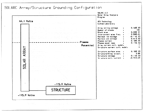 |
| Figure 7. The solar array and structure configuration |
Materials
Up to two elements present on both the solar array and the spacecraft structure
may be specified. The elements are selected from the list of elements used for
the plasma environment plus Kapton. These materials are not used in the
calculation of the current collection but are used to
determine erosion or sputtering rates.
Output
The following characteristics of the solar array and spacecraft are
determined:
- current collected by the specified solar array and spacecraft surfaces;
- array and structure voltages relative to the ambient plasma potential
(i.e. floating voltages);
- plasma current and power loss;
- erosion or sputtering of surfaces caused by energetic ion impingement.
References
Bohdansky, J., J. Roth, and H. L. Bay, An Analytical Formula and Important
Parameters for Low-Energy Ion Sputtering, J. App. Phys., 51, 2861, 1980.
Bond, R. A., The interaction of the Space Plasma with High Voltage Solar Arrays
and Large Structures, AEA Industrial Technology Report AEA-In Tec-0965,
1992.
Bond, R., T. Field, P. Hurford, and A. Martin, ESPIRE Version 1.0 Software
Users Manual, 1991.
Ferguson, D. C., The Energy Dependence and Surface Morphology of Kapton
Degradation under Atomic Oxygen Bombardment, p. 205 in 13th Space
Simulation Conference, NASA Conf. Publication CP-2340, 1984.
Matsunami, N., et al., Energy Dependence of the Yields of Ion-Induced
Sputtering of Monatomic Solids, Nagoya Institute of Plasma Physics Report
IPPJ-AM-32, 1983.
Matsuno, N., et al., Energy Dependence of Ion-Induced Sputtering Yields of
Monatomic Solids in the Low Energy Region, Nagoya Institute of Plasma
Physics Report IPPJ-AM-52, 1987.
Stevens, N. J., Summary of PIX-2 Flight Results over the First Orbit, AIAA
Paper No. 86-0360, 1986.
Viswanathan, R., G. Barbay, and N. J. Stevens, Environmentally-Induced
Discharge Transient Coupling to Spacecraft, NASA CR-174922, 1985.
Yamamura, Y., and J. Bohdansky, Few Collision Approach to Threshold Sputtering,
Vacuum, 35, 561, 1985.
Last update: Mon, 12 Mar 2018


